GUIDES
CLICK ON THE GUIDE OF YOUR CHOICE
SIMPLE INDEXING
Figure 2. illustrates a simple indexing mechanism. It consists of a 40-tooth worm wheel fastened to the work spindle, a single-cut worm, a crank for turning the worm shaft, and an index plate and sector. since there are 50 teeth in the worm wheel, one turn of the index crank causes the worm wheel and consequently the spindle to make 1/40 of a turn; so 40 turns of the index crank revolve the spindle one full turn.
(a) Suppose it is desired to cut a reamer
with 8 equally spaced teeth. Since 40 turns of the index crank turn the spindle
one full turn, 1/8 of 40 or 5 turns of the crank after each cut will space the
reamer for 8 teeth. If it is desired to space equally for, say, 10 teeth, 1/10
of 40 or 4 turns would produce the correct spacing,
(b) The same principle applies whether the divisions required
divide evenly into 40. for example, if desired to index for 6 divisions, 6
divided into 40 equals 6-2/3 turns; similarly, to index for, say, 14 spaces, 14
divided into 40 equals 2-6/7 turns. These examples may be multiplied
indefinitely and from them the following rule is derived;
(c) To determine the number of turns of the index crank
needed to obtain one division of any number of equal divisions on the work,
divide 40 by the number of equal divisions desired (provided the worm wheel has
40 teeth which is standard practice).
|
|
|
Figure 2 Simple indexing mechanism |
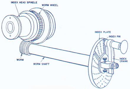
The index plate (figure 2) is a circular plate with a series of six or more circles of equally spaced holes; the index pin on the crank can be inserted in any hole in any circle. With interchangeable plates regularly furnished with most dividing heads, the spacing necessary for most gears, bolt heads, milling cutters, splines, etc., can be obtained. The following are the two most commonly sets of plates used as standard equipment.
Type 1 has 3 plates of 6 circles each, drilled as follows:
Plate 1 - 15, 16, 17, 18, 19, 20 holes.
Plate 2 - 21, 23, 27, 29, 31, 33 holes.
Plate 3 - 37, 39, 41, 43, 47, 49 holes.
Type 2 has one plate drilled on both sides with circles divides as follows;
First side - 24, 25,28, 30, 34, 37, 38, 39,
41, 42, 43 holes.
Second side - 46, 47, 49, 51, 53, 54, 57, 58, 59, 62,
66 holes.
The two following examples show how the index plate is used to obtain any desired part of a whole spindle turn and, consequently, the work by simple indexing:
(a) First example: To mill a
hexagon.
Procedure: Using the rule previously given, divide 40 by 6,
which equals 6-1/2 turns, or six full turns plus 2/3 of a turn on any circle
whose number of holes is divisible by 3. Therefore, 6 full turns of the crank
plus 12 spaces on an 18-hole circle, or 6 full turns plus 26 spaces on a 9-hole
circle.
(b) Second example: To cut a gear of 42 teeth.
Procedure: Using the rule again, divide 40 by 42 which equals
40/42 or 20/21 turns, or 40 spaces on a 42-circle, or 20 spaces on a 21-hole
circle. To use the rule given, select a circle having a number of holes
divisible by the denominator of the required fraction of turn reduced to its
lowest terms (What this means is try to find a plate with either 21-holes or
42-holes).The number of spaces between holes gives the desired fractional part
of the whole circle. when counting holes, start with the first hole ahead of the
pin.
The sector (figure 3) indicates the next hole in which the pin is to be inserted and makes it unnecessary to count holes when moving the index crank after each cut. It consists of two radial, beveled arms which can be set at any angle to each other and then moved together around the center of the index plate. Suppose that as shown in figure 3 it is desired to make a series of cuts, moving the index crank 1-1/4 turns after each cut. Since the circle illustrated has 20 holes, turn the crank one full turn, plus 5 spaces, after each cut. Set the sector arms to include the desired fractional part of a turn, or 5 spaces, between the beveled edges of its arms, as shown. If the first cut is taken with the index pin against the left-hand arm, to take the next cut, move the pin once around the circle and into the hole against the right-hand arm of the sector. Before taking the second cut, move the arms so that the left-hand arm is again against the pin; this moves the right-hand arm another five spaces ahead of the pin. Then take the second cut, repeat the operation, etc., until all the cuts have been completed. (Although not necessary, it is good practice always to index clockwise on the plate.)
 |
|
Figure 3 Index plate and sector |